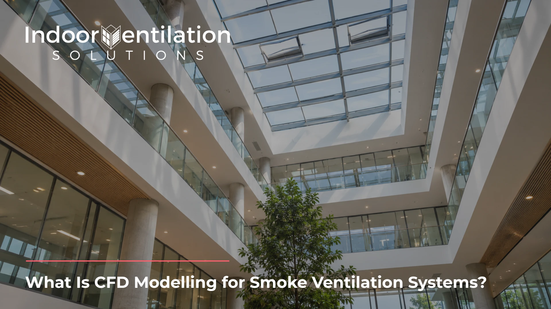
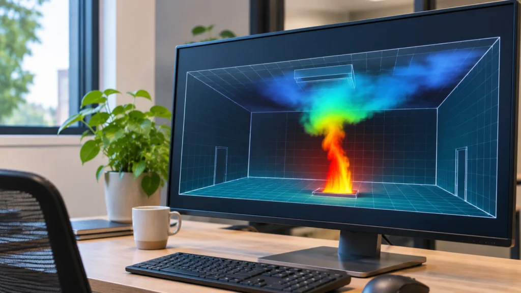
CFD stands for computational fluid dynamics. CFD smoke modelling in Ireland uses it to predict how smoke and heat will move through a specific building in a fire. That lets a smoke ventilation design be tested before a single vent is installed.
The animations CFD produces can be persuasive. The catch is that a CFD model’s results depend on what it was told to assume, and colourful output in a CFD report can hide those assumptions from the person approving the design.
A hand calculation treats the space more like a box filling with smoke. It can work well for a regular floor plate, depending on the design, and is the approach covered in the smoke ventilation system design guide.
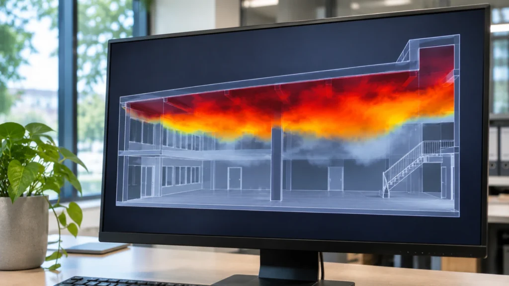
A CFD simulation follows smoke movement around beams and through connected floors. It shows where hot smoke travels, how deep it gets and whether escape routes stay usable.
How Does CFD Smoke Modelling Work?
CFD smoke modelling works in three stages, pre-processing, simulation and post-processing, as Engineers Ireland describes them. In pre-processing, the engineer builds a 3D model of the space and divides it into a large number of small cells.
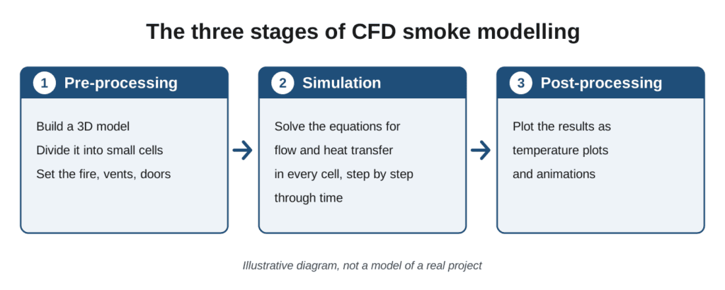
Then comes the fire and everything acting on it: the size and growth of the design fire (the assumed fire a system is sized against), the vents and fans, the doors, the routes replacement air takes into the building.
Each of those is an input the engineer has to choose, and each is a question you can put to the report.
In the simulation stage, the software solves the equations for fluid flow and heat transfer in every cell, step by step through time. These are the Navier-Stokes equations, which describe how fluids move.
Post-processing turns the numbers into the temperature plots and animations that a report presents.
What Is CFD Used For in Smoke Ventilation Design?
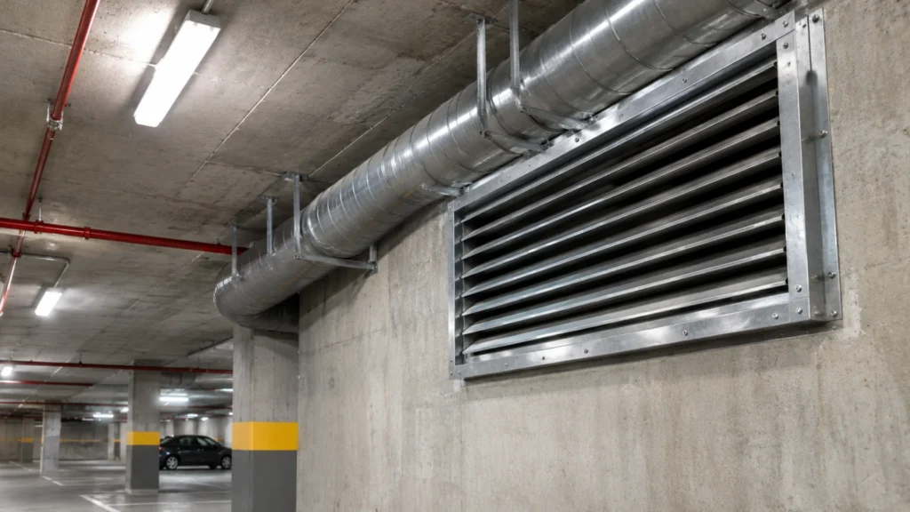
CFD analysis is used to test whether a proposed smoke ventilation layout does its job. The position of vents and fans, the size of openings and the supply of replacement air can all be tried against a fire scenario.
A clear example is replacement air. A mechanical extract system that pulls smoke out faster than air can enter does not reach its designed extraction rate, a failure the design guide covers under design failures.
A model that includes the inlet paths shows the shortfall before anything is built.
Wind belongs in the model too. A roof vent on the windward face can be pressurised by the wind instead of assisted by it, as the design guide explains in its section on wind as a design variable.
When Is CFD Smoke Modelling Required in Ireland?
Technical Guidance Document B (TGD B) does not mention CFD by name, so the guidance does not require it as standard. It is prima facie guidance for common, non-complex buildings, so following it will, on its face, indicate compliance with Part B of the Building Regulations.
Designers may take another route, but the requirements of Part B should still be proven (Para 0.2), and the building control authority may require evidence of it (TGD B Introduction). Very complex or very unusual buildings may fall outside what the guidance suits (Para 0.1.2).
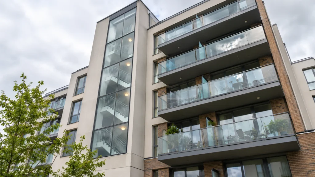
Some provisions name the proof directly. In buildings containing flats, the performance of a smoke control system serving corridor spaces should be proven by fire engineering analysis once the topmost floor is above 30 m (Para 1.6.6.3.1(b)).
Firefighting lobbies in buildings above 30 m call for a mechanical system, or an equivalent natural system, proven by fire engineering analysis (Para 5.5.6.4(e)).
Neither provision asks for CFD by name. Both ask for fire engineering analysis, and CFD is one way to carry it out. A hand calculation can be enough for a straightforward layout, while CFD suits layouts that a hand calculation can’t reasonably approximate, such as atria, connected floors and unusual shaft arrangements.
The report has to satisfy whoever accepts the design. Agree the approach with the people who will review it before modelling starts.
What Does a CFD Smoke Modelling Report Show?
The main outputs are smoke layer height, visibility, air temperature and the concentration of gases such as carbon monoxide. Each is tracked over time at points such as escape routes and stair entries, and compared with its success criteria, which decide whether conditions stay tenable for escape.
TGD B asks for tenable conditions for means of escape in the corridors and lobbies of buildings containing flats (Para 6.6.2).
Results are best read as predictions under the stated assumptions, so treat them as evidence for the design, not a guarantee of how a real fire will behave.
A CFD model is run before installation. It does not test what was installed, which is the job of commissioning and testing.
TGD B says active fire safety systems should be commissioned, tested and certified at completion (Para 0.8). Smoke ventilation commissioning in Ireland covers that stage.
What Software Is Used for CFD Smoke Modelling?
One program used for this work is the Fire Dynamics Simulator (FDS). It is free, open-source software from the US National Institute of Standards and Technology, and it is a computational fluid dynamics model of fire-driven fluid flow.
It has an emphasis on smoke and heat transport from fires. Its companion program, Smokeview, displays the results. If a report names FDS, this is the program behind it.
How Do You Check a CFD Smoke Modelling Report?
Check a CFD smoke modelling report by putting six questions to it. They are written for architects, developers and facilities managers who receive these reports.
Were the CFD success criteria agreed first?
The objectives, scenarios and success criteria should be agreed and written down before the analysis starts, with a source cited for the criteria. Without them, you can’t tell what the results are measured against.
Is the design fire justified?
Only if the report cites a source for it, including its size and growth. It also tests the fire in the worst credible positions and justifies any credit taken for sprinklers or other fire protection.
Does the model show replacement air, wind and vent area?
It should show all three. Look for the replacement air paths and the wind exposure where it matters, and check that the report states which vent area the model used. TGD B takes natural vent area as the geometric free area, the total unobstructed cross-sectional area (Para 6.1.4). Vents conforming to I.S. EN 12101-2, the standard for natural smoke and heat exhaust ventilators, may achieve it.
Do the modelled fans and vents behave realistically?
They should, and that means allowing for start-up time: fans and vents take time to reach full performance.
Are the CFD model’s cells small enough?
The cells need to be small enough to resolve the fire plume and the vents. A grid sensitivity check, which shows the result doesn’t change with a finer grid of cells, is part of showing a model can be relied on. The report should include one or explain why it wasn’t needed.
Could a reviewer reach the same CFD conclusion?
It could if the report gives enough detail to repeat the analysis, with results plotted against the stated success criteria. It is also fair to ask what experience the modeller has on similar schemes.
Planning a Smoke Ventilation System in Ireland?
If you have a live project at specification or review stage, talk through your project with Indoor Vent before the design is locked in.
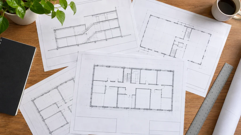
It helps to arrive with the building drawings, any fire strategy already written and, if a CFD report is on the table, the six questions above.
And when the next CFD report arrives, turn past the animations and read the assumptions first.