
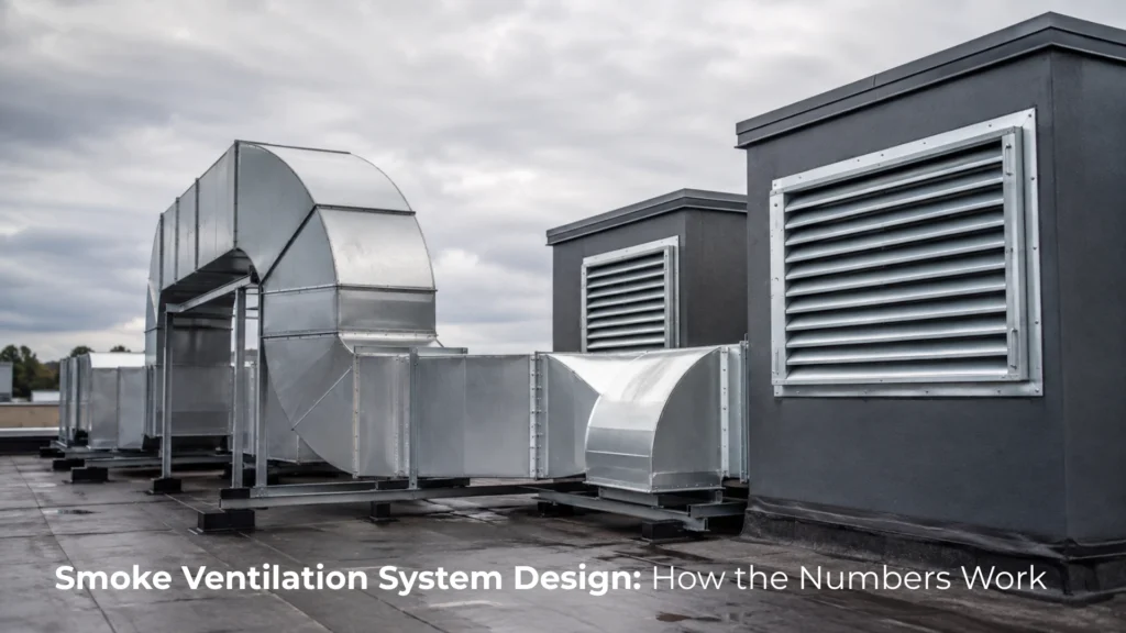
Smoke ventilation system design is the calculation stage that decides how much smoke a building will produce in a fire, how fast that smoke needs to leave, and exactly what size of vent, shaft or fan makes that possible within a survivable window. Most of that calculation never gets checked against the actual building it’s protecting, which is how a system can look fully compliant on a spec sheet and still fail in the first ninety seconds of a real fire.
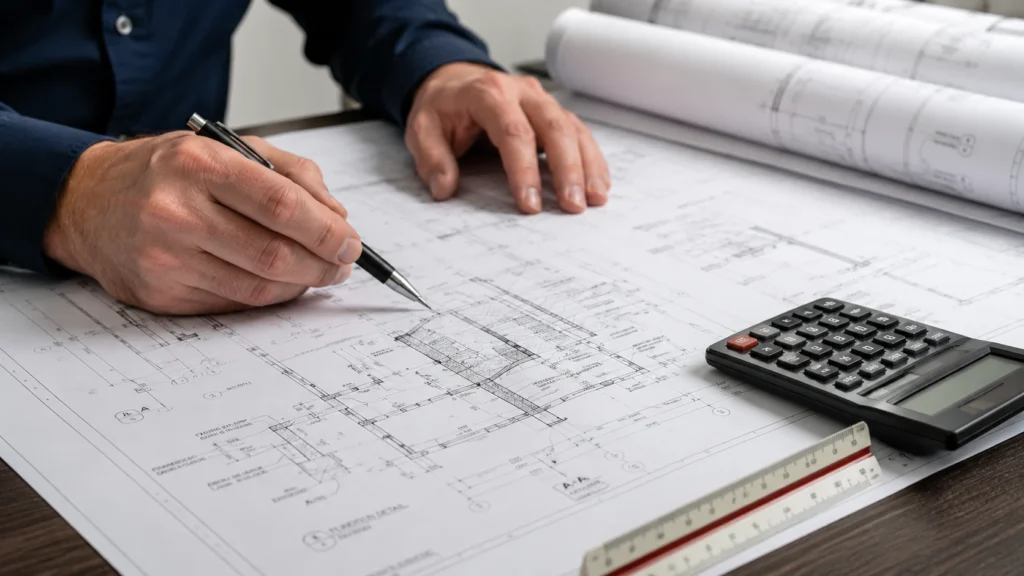
What Does Smoke Ventilation Design Actually Involve?
Most guidance on smoke control systems stops at what a system does and which components are involved. That’s useful for understanding the concept. It tells you nothing about how an engineer actually gets to those numbers for a specific building. That decision comes from a calculation, and the calculation starts with the fire itself, long before it reaches the equipment.
What Does TGD B Section 6 Actually Require?
TGD B Section 6 doesn’t just say a building needs smoke ventilation. It sets out, building type by building type, what has to be achieved: ventilation of protected stairway enclosures, ventilation of lobbies to protected stairways and lifts, and separate provisions for firefighting lobbies depending on whether vents open directly to the exterior or through a smoke shaft, above or below ground. Atria, car parks, buildings containing flats and shopping centres each get their own subsection, because a single blanket free area figure doesn’t hold across all of them.
This matters at design stage because Section 6 sets the target the calculation has to hit, not the components used to hit it. A system that satisfies the free area guidance for a common corridor but ignores the separate provisions for firefighting lobbies isn’t compliant with half the section it’s meant to answer to.

How Is the Design Fire Size Calculated?
Every smoke ventilation system is sized against an assumed fire, not a hypothetical one. Engineers select a design fire size, expressed as a heat release rate, based on the type of occupancy, the fuel load likely to be present, and how quickly that fire is expected to grow. A warehouse storing packaging materials produces a very different design fire to an office floor plate or a retail unit with dense combustible stock.
Get the design fire size wrong and everything downstream is wrong with it. The smoke mass flow rate, the clear layer depth, the vent free area, even the choice between natural and mechanical extraction, all trace back to that first number. It’s why a properly designed system references the specific building and its use, not a generic occupancy class pulled from a table without checking whether it actually applies.
What Is Smoke Mass Flow Rate?
Smoke mass flow rate is how much smoke a fire actually produces as it rises and mixes with air. Hot smoke rises because of buoyancy, drawing in cooler air as it climbs, so the mass reaching ceiling level is always greater than the mass produced at the fire itself. The taller the space, the more air gets entrained on the way up, and the more smoke the ventilation system has to be capable of extracting.
Floor-to-ceiling height now starts driving the design directly. A double-height atrium and a standard three-metre office floor demand entirely different extraction rates for what might be an identical design fire, because the smoke has travelled a different distance before it needs to be dealt with.

What Is Clear Layer Depth and Why Does It Matter?
Clear layer depth is the height of smoke-free air that has to be maintained above floor level long enough for occupants to escape and firefighters to enter. It’s calculated from how long people realistically need to reach an escape route from the deepest part of the building, and it must remain tenable for that entire window.
Long before anyone debates natural versus mechanical extraction, this requirement has usually already ruled half the options out. A building with long travel distances to the nearest protected corridor needs a longer tenability window, which usually means a larger extraction rate or a shaft placed differently, not just a bigger vent bolted onto the same layout.
Free Area Is a Calculation, Not a Spec Sheet Number
Two numbers get used for vent sizing. Only one of them actually clears smoke. Vent sizing gets reduced to a single figure on a lot of drawings, and that figure is usually the wrong one to trust blindly. The geometric free area of an opening, meaning its raw physical dimensions, is a poor proxy for smoke clearance. The aerodynamic free area is the number that matters, accounting for the coefficient of discharge of that specific vent under real airflow conditions, tested and declared in accordance with EN 12101.
Two vents with an identical geometric opening can have meaningfully different aerodynamic free areas depending on louvre angle, blade design and how the vent has been installed. Specifying by geometric area alone can leave a shaft or roof vent short of the extraction rate the design fire actually requires, even though it looks correctly sized on paper.
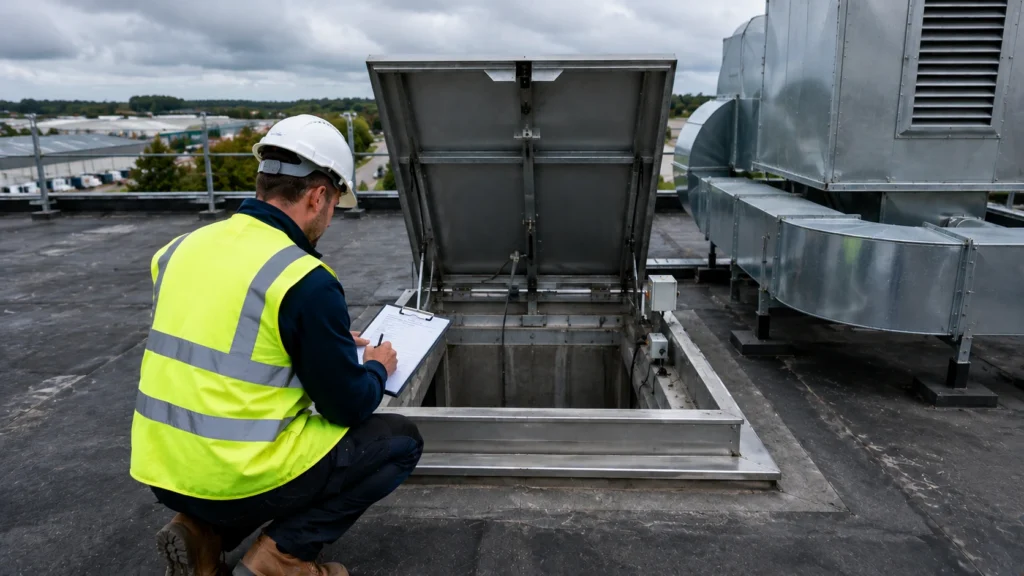
What Decides Natural, Mechanical or Pressurisation Design?
Natural smoke ventilation relies on buoyancy and wind to move smoke through vents and shafts without mechanical assistance. It works well in taller spaces with a strong stack effect, but loses reliability in deep floor plates, basements, or layouts where smoke has no clean path upward and out.
Mechanical extraction takes over where that natural path runs out, in deep-plan buildings and below-ground car parks especially, and needs a controlled supply of fresh air to replace what it removes, or the calculated extraction rate never materialises. Pressurisation solves a different problem: it protects stairwells and firefighting shafts by holding them at higher pressure than the fire floor, so smoke is kept out rather than extracted.
A building that supports a fully natural system on one elevation might still need mechanical extraction on a courtyard-facing side with no usable wind path. The building’s shape drives that choice.
When Does a Design Need CFD Modelling?
Standard calculation methods work well for straightforward geometries: a rectangular floor plate, a single stairwell, a predictable travel distance. They start to break down in atria, interconnected floors, unusual shaft arrangements, or any building where smoke behaviour can’t reasonably be approximated by hand calculation.
Computational fluid dynamics modelling earns its cost in exactly this situation. A CFD model simulates how smoke actually moves through the specific geometry of the building, testing whether the proposed vent sizes and shaft positions hold a tenable environment for the required evacuation time, rather than assuming a simplified case applies. It validates the underlying calculation against a building too complex for the standard method to be trusted on its own, before a single vent gets installed.
Wind Is a Design Variable, Not an Afterthought
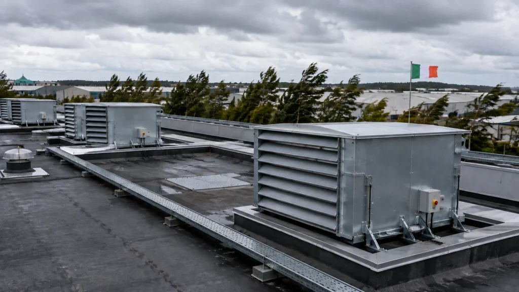
Natural smoke ventilation depends on wind as much as it depends on heat, and wind doesn’t behave consistently around a building. Roof-mounted vents on the windward face can be pressurised by incoming wind rather than assisted by it, actively resisting the smoke trying to escape, while the same vent on a leeward face might perform exactly as intended.
Surrounding buildings, terrain and the height of the structure itself all change how wind behaves at vent level, and a design that ignores this can pass a paper calculation and still underperform on site. Vent placement has to be decided alongside the calculation, not after it, because a design that works on one elevation of a building can’t always be mirrored on another without checking the exposure again.
What Are the Most Common Smoke Ventilation Design Failures?
Three mistakes account for most smoke ventilation systems that fail inspection or underperform on site.
The first is undersized free area, usually because geometric area was specified instead of aerodynamic free area, or because the vent’s actual coefficient of discharge was never checked against the manufacturer’s declared figure.
The second is missing make-up air. A mechanical extraction system pulling smoke out faster than replacement air can enter doesn’t achieve its designed extraction rate. It just fights itself.
The third is non-compliant shaft geometry: a smoke shaft sized or routed to suit the building’s structural grid rather than the free area and travel distance calculation it’s meant to serve. It looks correct on a floor plan and fails the moment it’s tested against the actual smoke mass flow rate it needs to handle.
Need a Smoke Ventilation System Properly Designed?
A smoke ventilation system that’s been properly designed holds up when someone actually checks it against Technical Guidance Document B, when a fire engineer, a building control officer or an insurer asks to see the calculation behind it. The reasoning behind the vent size, the shaft depth and the extraction method chosen needs to survive that question too. A correctly sized system still depends on regular inspection and testing to confirm it performs the way the original calculation assumed, a separate discipline in its own right.
If you’re at the stage where a general overview of smoke control no longer answers the questions your project is actually asking, the next step is a conversation with our smoke ventilation design service.