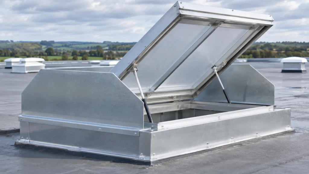
Geometric free area vs aerodynamic free area is the difference between how big a smoke vent’s opening is and how much smoke it actually passes. Geometric free area is the physical opening. Aerodynamic free area is that opening adjusted by the vent’s coefficient of discharge, which allows for airflow losses.
A vent can pass a drawing review and still fall short of what the design needed.
Irish guidance adds a twist. Technical Guidance Document B (TGD B) asks for the geometric measure for lobby and corridor vents and the aerodynamic one in the stage ventilation provisions. Which one your project needs depends on where the vent sits.
How Do Geometric and Aerodynamic Free Area Compare?
| Geometric free area | Aerodynamic free area | |
| What it measures | The clear opening of the vent at its narrowest point, at right angles to the airflow | The effective opening once airflow losses through the vent are counted |
| How you get it | From the vent’s dimensions and drawings | From the manufacturer’s declared figure for the vent |
| How the two relate | The starting figure | Geometric area multiplied by the coefficient of discharge |
What Is Geometric Free Area and How Is It Measured?
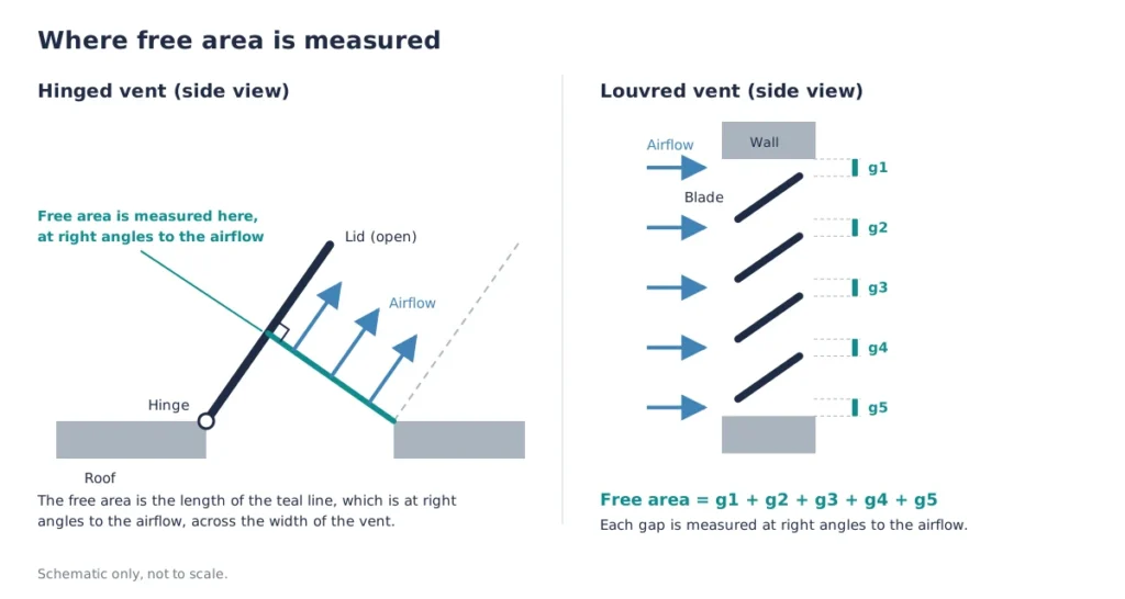
The geometric free area of a smoke vent is the clear space left once the vent is open and its own parts are out of the way. TGD B takes the smallest cross-section of that space, measured at right angles to the direction the air travels (Para 6.1.4 of Volume 1, 2024, reprinted January 2026, corrections incorporated). Our smoke ventilation system design guide shows where this figure sits in the wider calculation.
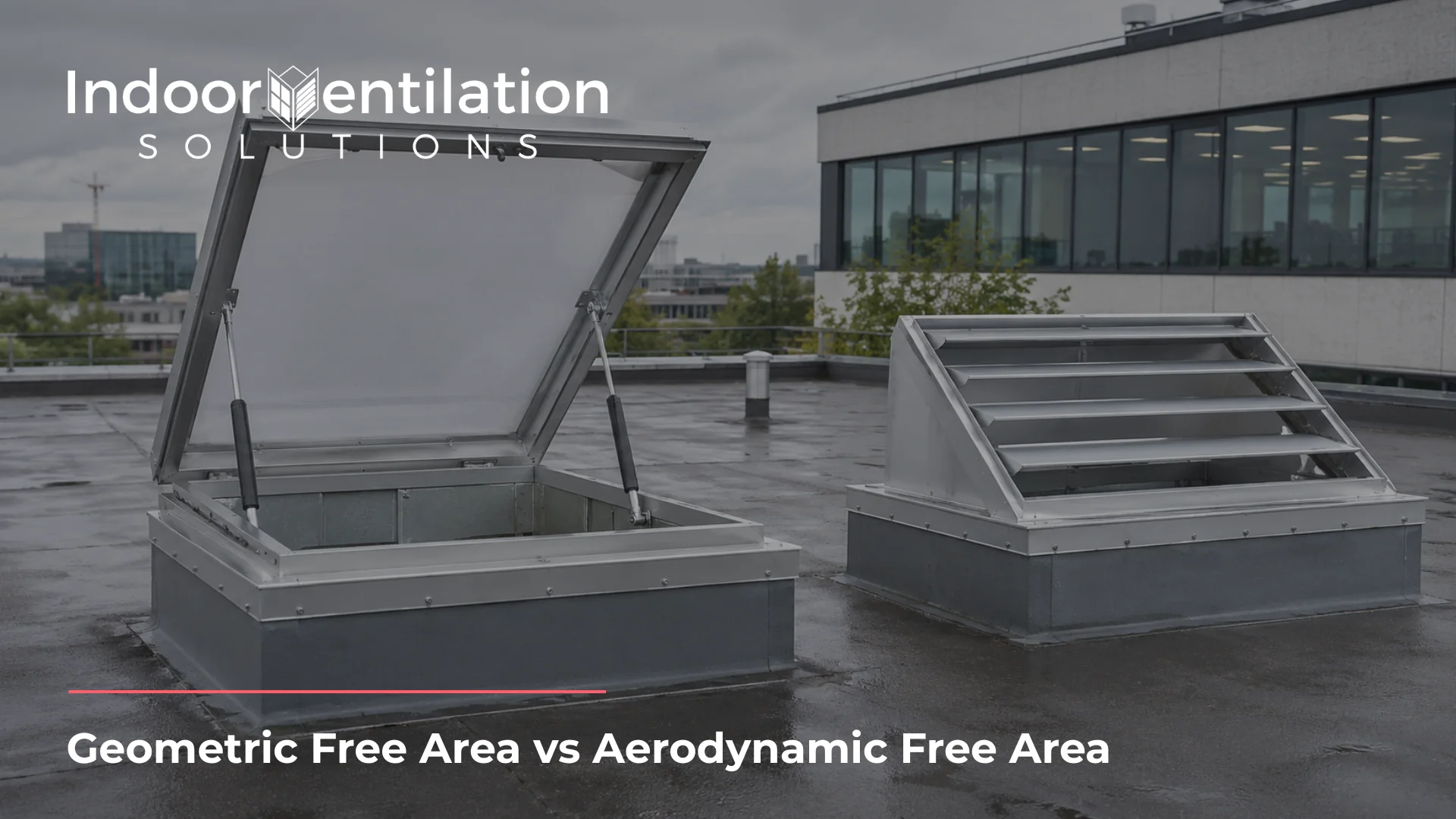
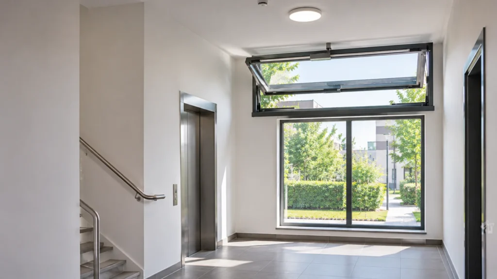
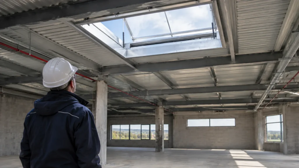
On a hinged vent, such as a roof-mounted automatic opening vent (AOV), you measure the AOV free area at right angles to the airflow.
On a louvred vent, you add up the gaps between the blades, so the size of the opening alone does not give you the free area. TGD B’s Diagram 78 shows both.
Publications use “geometric” in more than one way. Building Engineer, the journal of the UK’s Chartered Association of Building Engineers, carries an article by a fire engineer that cites British Standards BS 7346-8:2013 and BS EN 12101-2:2017.
In that definition, geometric area is the opening measured in the plane of the construction surface where it meets the vent.
TGD B defines geometric free area differently, as set out above. A figure labelled geometric on a data sheet should say which one it is.
What Is Aerodynamic Free Area?
Aerodynamic free area is the geometric figure adjusted for airflow losses through an open vent. Blades, frames and the lid can affect how smoke moves through it.
I.S. EN 12101-2:2017 is the Irish adoption of the European standard for natural smoke and heat exhaust ventilators, and its Annex B deals with aerodynamic free area. BS EN 12101-2 is the British adoption of the same standard, so on Irish paperwork cite the I.S. designation.
Our EN 12101 guide explains the standard part by part.
A declared figure applies to the vent in the configuration it was declared for. Fit wind deflectors, leave them off, or change the frame, and the number may not follow. Ask the manufacturer for the declared figure and the configuration it covers.
How Do You Calculate Aerodynamic Free Area?
Multiply the geometric area by the coefficient of discharge, written Cv, to get the aerodynamic free area. Building Engineer, cited above, gives the relationship this way.
Cv compares the flow a vent achieves under specific conditions with the flow an unobstructed opening of the same geometric area would pass in theory.
A single vent shows the aerodynamic free area calculation. Say a vent has a geometric free area of 2.0 m² and a Cv of 0.5, a figure invented for this example. Its aerodynamic free area is 2.0 × 0.5 = 1.0 m², half of its geometric free area.
In practice, take the declared aerodynamic free area from the manufacturer rather than calculating it. Do not reuse a Cv from a different vent.
The arithmetic matters most when someone has quoted the wrong measure.
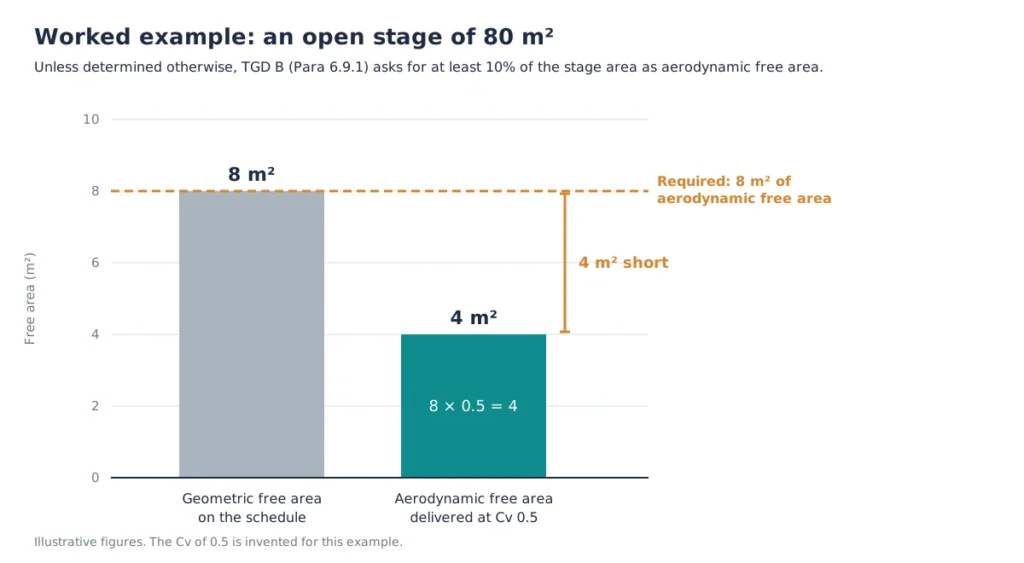
Take an open stage of 80 m². Unless determined otherwise, TGD B (Para 6.9.1) asks for a combined total aerodynamic free area of at least 10% of the stage area, so 8 m². A schedule of ventilators with a combined geometric free area of 8 m² looks like a match.
Give those ventilators the same Cv of 0.5 and they pass 8 × 0.5 = 4 m². That is half of the 8 m² the provision asks for, from a schedule that looked like a match.
What Does Net Free Area Mean?
One UK manufacturer’s guide treats net free area, effective free area and aerodynamic free area as one thing, while another UK guide uses “free area” for the opening left after the frame, blades and motor are deducted.
TGD B does not use the term net free area at all. Its glossary defines free vent area as the geometric open area of a ventilator. That means a figure labelled net free area on a data sheet does not tell you, on its own, which TGD B measure it matches.
Technical Guidance Document F (TGD F, 2019), the Irish ventilation guidance, defines free area the same way and adds a further measure for background ventilators, equivalent area, which is the area of a single sharp-edged hole that passes the same airflow at the same pressure difference as the vent being tested.
It says equivalent area is always less than free area (Para 1.1.15).
Which Free Area Does TGD B Use in Ireland?
It depends on the provision. Para 6.1.4 takes the vent area as the geometric free area, and the 1.5 m² lobby and corridor vent figures in Para 6.3.2(a) and Para 6.6.2.1(a) are measured that way. Our stairwell smoke ventilation guide covers those figures for stairs, lobbies and corridors.
Over a stage, the wording changes to aerodynamic free area (Paras 6.9.1 and 6.9.2, as in the 80 m² example above). If a building has a theatre, hall or auditorium with a stage, one design can carry both measures.
Approved Document B is English guidance, and its Appendix D (paragraph D5) lets a designer measure free area either by declared aerodynamic free area or by geometric free area.
TGD B does not offer that choice in Para 6.1.4 and gives no conversion factor between the two, so an English rule of thumb is not an Irish requirement.
TGD B is also guidance, not the only route. A designer can take another approach, and the requirements of Part B should then be proven (Para 0.2). Where a fire engineer’s strategy specifies an aerodynamic free area, check the vents against that figure.
How Do You Check Free Area When Specifying Vents?
The drawing, the data sheet and the smoke model are the three places to check.
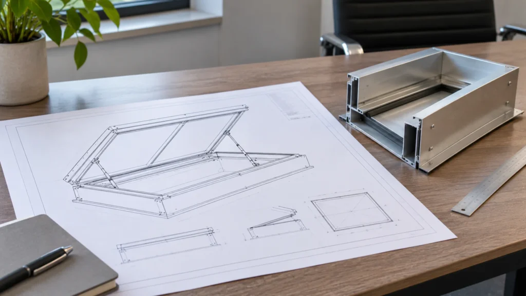
Start with the drawing, where a vent is labelled with an area and nothing else. A bare “free area” leaves the reviewer guessing whether it is geometric, aerodynamic or the structural opening. Label every figure with its measure.
On the data sheet, a product may list a geometric figure and an aerodynamic figure side by side, and the two figures may relate to different configurations.
Match the figure to the measure the design asks for, and the configuration to what is being supplied. A substitute vent of the same size does not guarantee the same aerodynamic free area.
A computational fluid dynamics (CFD) smoke model that draws a vent as a plain hole at its geometric area assumes it passes smoke with no losses, so it can overstate what the real vent delivers. Our CFD smoke modelling guide lists the questions to put to a report, including which vent area the model used.
Need Help With Smoke Ventilation in Ireland?
If a specification gives a free area without saying which kind, raise it before anything is ordered. You can contact the Indoor Vent team through the smoke ventilation page or at Info@indoorvent.ie.